Mini Satellite-Antenna Rotator Mk1 - SARCNET
Jump to navigation
Jump to search
Reference
Hardware Mk1b
Hardware Assembly
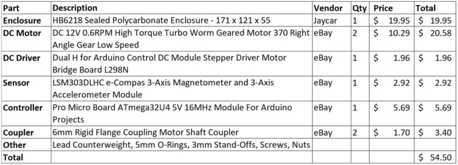
- The hardest part of the build was precision-marking and drilling the motor mounting holes. We recommend sticking adhesive paper labels to the diecast box, scribing construction lines on them using a digital vernier caliper, center-punching and drilling pilot holes first. A drawing of the motor mounting holes can be found in the motor datasheet here. Check three times - drill once.
- Countersink the motor shaft holes on the inside of the rotator case and slip 5mm o-rings over the motor shaft before assembly for ingress protection.
- Add two flat washers to the AZ motor mounting bolts on the side near the lid to counter the chamfer in the rotator case.
- Install a cable gland on the bottom of the rotator case for the PC/Battery and Sensor cables.
- Install the Motor Drivers to the case using countersunk bolts and stand-offs.
- Install the Arduino Pro Micro against the case wall using two layers of double-sided tape on its flat side.
- Prepare an Extra Heavy Duty Speaker Tripod. Try Altronics C0520A. Remove the speaker bracket if fitted.
- Attach a 6mm shaft-hub to the top of the tripod using a 25mm irrigation-pipe threaded plug, 3mm cheese-head bolts, flat washers, spring washers and nuts. Fix with self-tapping screws to the tripod. Replace the grub screws on the shaft hub with cheese-head bolts or cap screws to obtain additional torque.
- Attach the rotator's AZ motor shaft to the tripod and tighten the hub screws.
- Round the sharp edges of a lift arm made from 500x30x30x3mm aluminium angle.
- Make a counterweight from a 101x51x25mm diecast aluminium box: Altronics H0451, Hammond 1590G or similar. Filled with lead to a total weight of 860g/1.9lb.
- Attach the counterweight to one end of the lift arm with self-tapping metal screws.
- Attach the Arrow antenna to the lift arm using Velcro. This is for quick release of the antenna and hand-held operation, if required.
- Attach a 6mm shaft-hub to the lift arm close to the balance point. Ours was 140mm from the antenna end. A slight front-heavy balance offset will reduce backlash.
- Attach the lift arm to the rotator's EL motor shaft using the 6mm shaft-hub and tighten the hub screws.
- Enclose the sensor in 12mm double-wall heatshrink tube and crimp the front end. Mount the flat side of the sensor against the boom with a velcro strap around the boom. See: Sensor Orientation for details. Keep the sensor away from the VHF/UHF driven elements to avoid RF interference to the sensor. Don't use high power for satellites. Use ferrites on the I2C lines if necessary.
Sensor Orientation
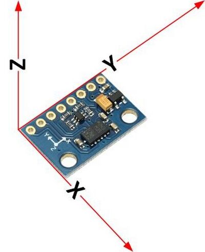
- This project is using a LSM303DLHC sensor to measure Magnetic Fields and Gravity to determine sensor orientation. The diagrams show their correct orientation for the LSM303DLHC sensor.
- The sensor is attached to the antenna boom and is aligned with the antenna reference axes (X, Y and Z shown in red above) as follows: With the antenna horizontal and pointing North, X points due East, Y points due North, along the antenna boresight, and Z points up.
- Please disregard any axes printed on the PCB.
- Because the flat side of the sensor board is attached on the top of the antenna boom, with the long side of the sensor board parallel to the boom, the sensor axes (X', Y' and Z', as sometimes printed on the PCB) are not the same as the antenna reference axes (X, Y and Z) as used in our software and our original article. Instead, X = -Y', Y = X' and Z = Z'. Also, the gravity field vector G is the opposite of the device acceleration vector A.
- Therefore the following transformations of the Magnetic (M) and Gravity (G) vectors are applied by our software:
- MX = -MY', MY = MX', MZ = MZ', GX = AY', GY = -AX', GZ = -AZ'.
Electrical Assembly (Mk1b)
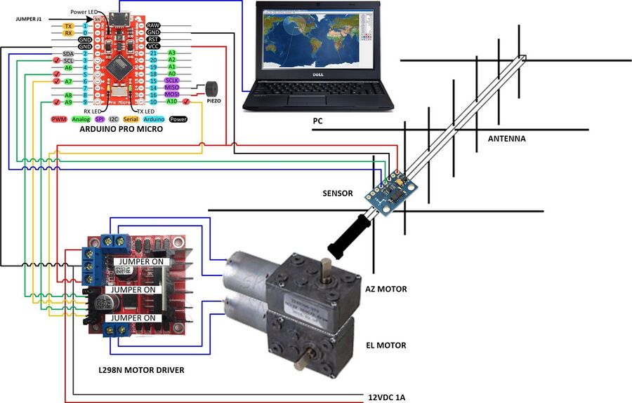
- Important: Bridge Jumper J1 on the Arduino Pro Micro.
- Connect Pro Micro SDA, SCL, GND and VCC to the Sensor SDA, SCL, GND and VIN pins via a long flexible cable. We use flat telephone cable.
- Connect Pro Micro pins 5, 6, 9 and 10 to the Motor Driver terminals (IN1, IN2, IN3 and IN4 respectively).
- Connect Pro Micro pins 16 (+) and 14 (-) to a Piezo Buzzer to assist with calibration.
- Connect Pro Micro GND to the Motor Driver GND terminal.
- Connect Motor Driver OUT1, OUT2 to the AZ Motor and OUT3, OUT4 to the EL Motor (be prepared to reverse these during testing as the motor pins are not polarised).
- Connect Motor Driver 12V and GND terminals to your 12V supply via a cutoff switch and fuse (Caution: Don't connect until safe: The motors may move)
- Connect Pro Micro USB port to the PC USB port. To fit the cable through the gland, cut a standard micro USB cable in half and re-terminate it. This port powers both the Pro Micro and Motor Driver electronics.
Testing the Arduino Pro Micro stand-alone
- Install the Arduino IDE from https://www.arduino.cc/en/Main/Software. Note: Give the drivers ample time to install.
- Connect the Arduino Pro Micro via a micro USB cable to the PC USB port.
- Open the Arduino IDE
- Select File | Examples | 01.Basics | Blink
- Select Sketch | Verify/Compile (Ctrl+R). You should see "Compiling sketch..." followed by "Done compiling"
- Select Tools|Board: Arduino Leonardo
- Select Tools|Port: COMnn (Arduino Leonardo)
- If you don't see COMnn (Arduino Leonardo) you may have to determine the virtual serial port used by the controller:
- On Linux start a terminal window and type: dmesg | grep "USB ACM device" Make a note of the tty device.
- On Windows start device manager and look under "Ports" for "USB Serial Device" or "Arduino". Make a note of the "COM" number.
- Select Tools | Port and the COM port number you noted earlier.
- Select Sketch | Upload (Ctrl+U). You should see "Uploading...". The Arduino Pro Micro LEDs will flash 3 times. Then "Done uploading".
- This indicates that you can successfully compile and upload an Arduino file.
- Note: The Blink sketch does not blink the Pro Micro LED unless you add "#define LED_BUILTIN 17" to the start of the program and accept the compiler warning
- If you can't upload. May we suggest: Closing the IDE. Disconnecting and re-connecting the controller. Starting the IDE again and repeating steps 4 onwards.
Compilation Instructions
- Open the Arduino IDE.
- Select File|Preference to find out your sketchbook location.
- Open the Mini Satellite-Antenna Rotator Arduino code file (RotatorX.zip)
- Copy the RotatorX folder to your sketchbook location.
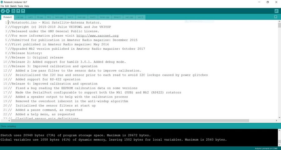
- Select File|Open|RotatorX|RotatorX.ino. You should see eleven files open in the IDE as shown below.
- Select Sketch Verify/Complile (Ctrl+R). You should see "Done compiling" and no errors (but please ignore any compiler warnings) as below.
Set to Work Instructions (Part 1)
- Check the motor and sensor configuration. Click on the Rotator6 tab and find the following lines.
- The line with the motor or sensor you are using should start with const the other unused types should start with //const. I.E. Comment out the devices you don't use.
- The following shows the configuration for the type 1b with L298N motor driver and LSM303DLHC sensor.
//Constants
//User configuration section:
//Please uncomment only one of each of the following MotorTypes, SensorTypes and SerialPort types:
//const int MotorType = PWMDIR; //Please uncomment this line for the LMD18200T DC motor driver.
const int MotorType = FWDREV; //Please uncomment this line for the L298N DC motor driver.
//const int MotorType = ACMOTR; //Please uncomment this line for the triac AC motor driver.
//const int SensorType = LSM303D; //Please uncomment this line to use the LSM303D sensor.
const int SensorType = LSM303DLHC; //Please uncomment this line to use the LSM303DLHC sensor.
- Connect the Mini Satellite-Antenna Rotator controller USB port to a PC or Raspberry Pi or whatever, but do not connect the 12V motor supply.
- Start the Arduino IDE and open the rotator sketch
- Press Upload to reboot the Arduino and start up the IDE Serial Monitor (button at top right).
- Select Carriage return from the dropdown box.
- Type b and then press Enter
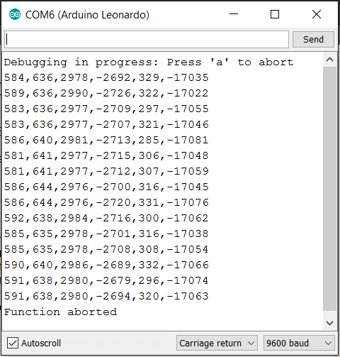
- You should see the raw sensor data (six numbers) as shown below. If you see "nan" or "ovf" there is a problem with the sensor or sensor connection.
- Type a and Enter to abort debug mode.
- You now have to run the calibration procedure at least for the first time before you can proceed.
Sensor Calibration Instructions
Set to Work Instructions (Part 2)
- Once calibration data is saved to the EEPROM you can continue to set the rotator to work.
- Make sure the 12V motor supply is disconnected. Connect the PC to the rotator using the USB cable.
- Start the Arduino IDE and open the rotator sketch.
- Press Upload to reboot the Arduino and start up the IDE Serial Monitor.
- In the IDE Serial Monitor type m<Enter> to enter the monitor mode.
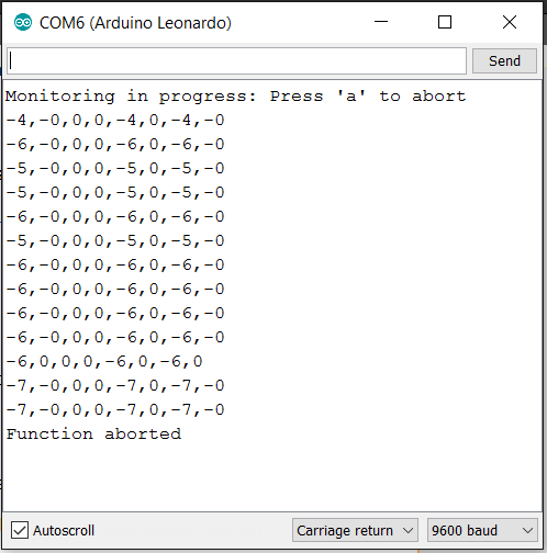
- You should see 8 separate rotator data points as shown below, comprising:
Current AZ, Current EL, AZ Setpoint, EL Setpoint, AZ Windup angle, AZ Windup State, AZ error, EL error
- Verify the Current AZ and EL numbers reflect the sensor true azimuth and elevation
- Make sure the lift arm is disconnected. Connect the 12V motor supply.
- Observe the IDE Serial Monitor display and observe the motor movement while looking directly at the motor shafts.
- Point the sensor North East. The first number should be between 0 and +90.
- Point the sensor North West. The first number should be between 0 and -90.
- Point the sensor 45 degrees Down. The second number should be between 0 and -90.
- Point the sensor 45 degrees Up. The first number should be between 0 and 90.
- Disconnect the 12V motor supply. Attach the rotator to the tripod. Attach the lift arm to the rotator. Attach the sensor along the boresight of the lift arm.
- Disconnect the USB cable.
- While carefully monitoring the lift arm, ready to disconnect the 12V motor supply if something goes wrong. Connect the 12V motor supply - there should be no movement.
- Connect the USB cable. The lift arm should swing around to 0 degrees AZ/EL and stop.
- Turn and tilt the tripod. The rotator should restore the lift arm to this home position.
- In the IDE Serial Monitor type 30 45<Enter>'. The lift arm should swing around to approximately 30 degrees AZ and 45 degrees EL.
- If everything is working properly you may like to repeat the calibration procedure more carefully if you wish.
Testing the AZ and EL motors with Arduino
- This process will help you to check whether your AZ and EL motors are in the correct position and are turning the right way:
- In the serial monitor set the setpoint to 0 0<Enter> (The first number controls the AZ set point while the second number controls the EL set point). This should rotate the motor to its default positions.
- set the AZ setpoint to any number between 0 and +90 (eg. 45 0<Enter> in the terminal). The AZ motor should now move clockwise.
- set the AZ setpoint to any number between 0 and -90 (eg. -45 0<Enter> in the terminal). The AZ motor should now move counterclockwise.
- set the EL setpoint to any number between 0 and +90 (eg. 0 45<Enter> in the terminal). The EL motor should now move clockwise.
- set the EL setpoint to any number between 0 and -90 (eg. 0-45<Enter> in the terminal). The EL motor should now move counterclockwise.
- If a motor moves in the wrong direction, reverse the motor wires by swapping the OUT connections on the appropriate Motor Driver board.
Installing Gpredict
Installing on Raspberry Pi
- Use a RPi Version 3 or 4 with built-in WiFi, or a version 2 with a USB WiFi dongle. Add a PiFace Real Time Clock if you want to use it portable.
- Start by downloading the the latest Raspberry Pi OS imager from here to create your micro SD card image.
- When your Raspberry Pi OS is installed and running, open a terminal window and execute the following commands.
sudo apt-get update
sudo apt-get upgrade
sudo apt-get install gpredict
Installing on MacOS
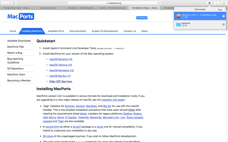
- Install MacPorts at: https://www.macports.org/install.php
- Install Gpredict in the terminal by entering
sudo port install gpredict
- Try to run Gpredict from the MacPorts folder
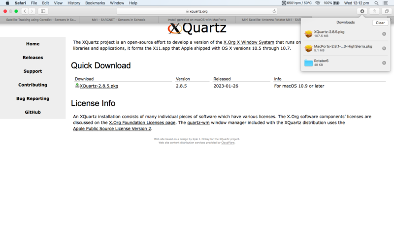
- If Gpredict does not want to run, try installing XQuartz at: https://www.xquartz.org
Install HAMLIB manually to get the absolute latest version
- Note the latest release number e.g. 4.5.5. Replace the actual number wherever you see this number below
cd ~/Downloads/
mkdir hamlib
cd hamlib
wget https://github.com/Hamlib/Hamlib/releases/download/4.5.5/hamlib-4.5.5.tar.gz
tar -xvzf hamlib*
cd hamlib-4.5.5
./configure
make
sudo make install
sudo ldconfig
- Plug the rotator into to a USB port and start the HAMLIB rotator control daemon in a terminal window:
rotctld -m 202 -r /dev/ttyACM0 -s 9600 -C timeout=500 -vvv
- Where: 202 is the model number for a rotator emulating AMSAT Easycomm II protocol
- If you are using a different port for your rotator, simply replace '/dev/ttyACM0' for whatever port you are using.
- Note that if using the rotctld command, ensure that your serial monitor is closed. You can open the serial monitor once the command has been executed.
- Plug the radio, via a CAT cable, into a USB port and start the HAMLIB rig control daemon in a terminal window:
rigctld -m MMM -r /dev/ttyUSB0 -s 38400 -T 127.0.0.1 -t 4532 -vvvvvvvv
- Where: MMM is the HAMLIB model number for your radio and 38400 is the CAT baud rate of your radio.
- See: https://github.com/Hamlib/Hamlib/wiki/Supported-Radios
Gpredict Configuration
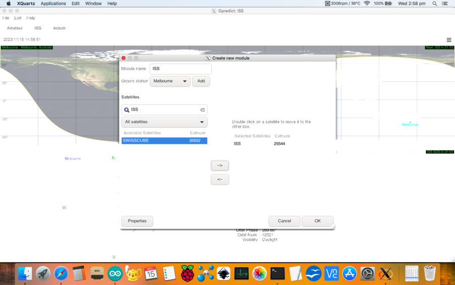
- Select File | New Module
- Enter Module Name: e.g. “MySats”
- Select Ground station: Add
- Enter ground station Name and Description and select your Location
- Select OK
- Select Ground station: e.g. Home for the MySats module
- Select Satellites (use categories and search to find them)
- Select OK
- Select Edit | Update TLE data from network. Select Close.
- Select Edit | Preferences | Interfaces
- Select Radio, Add New and Edit. Change the parameters for your radio.
- Select OK
- Select Rotator, Add New and Edit.
- Change Az type to 0 - 180 -360
- Select OK
- Select Module options / shortcuts (The small down-arrow on top right of the module)
- Select Radio Control
- Select a Target satellite and press Track
- Select your radio and press engage
- Select Module options / shortcuts (The small down arrow on top right of the module)
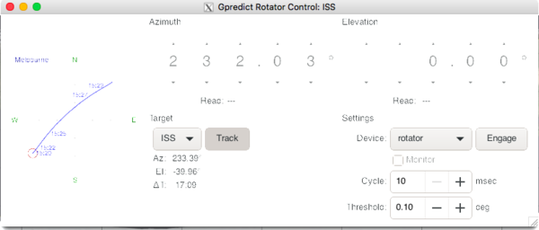
- Select Antenna Control
- Select a Target satellite and press Track
- Select your rotator, set tolerance to minimum and press Engage.
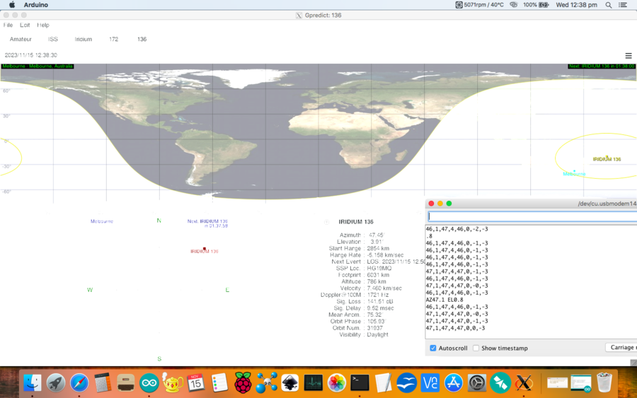
- When using Hamlib together with Gpredict the AZ and EL setpoint on the Arduino serial monitor should mirror the current satellite AZ and EL values on Gpredict.
- observe how the AZ and EL values on gpredict are the same as the set point on the serial monitor showing where the rotator should face.
- Also observe how the values of the current AZ and EL are very close to the setpoint values. This indicates that the rotator is moving along and tracking the satellite as it passes.
Operating Instructions
- Serial commands:
- Enter two integers AZ and EL in degrees separated by a space to manually control the rotator. e.g. 270 45<Enter> Note: AZ here works in either 0~180~360 or -180~0~180 degree format.
- r - Reset. Prints the calibration data. Resets the rotator to the home position and resets the windup value.
- b - Debug mode. Prints the raw sensor data: Mx, My, Mz, Gx, Gy and Gz.
- c - Calibrate mode. Displays the calibration data only when it changes.
- d - Demo mode. Tracks linearly through the following AZ/EL points in a cycle: 0/0, 90/90, 0/180, 90/90 0/0, -90/90, -180/0, -90/90, 0/0
- m - Monitor mode. Prints current AZ and EL, set points for AZ and EL, the AZ windup angle, the AZ windup state, the AZ and EL error.
- a - Abort Calibrate, Monitor or Demo mode
- e - Enter Magnetic Declination. e.g. e11.7<Enter>. It is positive for East or negative for West.
- s - Save Magnetic Declination and Calibration Data.
- h - Help
- p - Pause
Cautions
- Please read the following very carefully. We accept no responsibility or liability for the following:
- This is a DIY project for the experience builder. We are not responsible for your time, costs, tools, availability or substitution of parts.
- Beware of moving parts - Unit may move at any time without warning. Do not stand or permit anyone to stand in the vicinity of the operating unit.
- Beware of eye hazard - Moving satellite antennas are prickly. Eye protection is recommended.
- Beware of pinch hazard - Keep fingers away from moving parts.
- Beware of electromagnetic radiation hazard - Do not use with high power transmitters. Recommend 10 Watts maximum.
- Beware of electrocution hazard - Do not use near power lines.
- Beware of lightning hazard - Do not use in thunderstorms, rainy or windy conditions.
- Beware of fire hazard - The unit has no built-in over-voltage or over-current protection.
- Not suitable for unattended operation.
- Not suitable for fixed or permanent outdoor operation.
- Automatically connects to the Internet: Adult permission and charges may apply.
- Constant adult supervision of the operation is required to prevent injury, especially around children.
- Constant adult supervision of the operation is required to prevent damage to the unit, anything attached to the unit or anything in the vicinity of the unit.
- Constant adult supervision of the operation of radio transmitters is required at all times. You must check your licence conditions and operating frequency.
- Antenna, tripod, lift arm, mountings, cables or anything in the vicinity of the unit may be damaged under normal operation or due to software malfunction.
- The motors are light-duty and the antenna provides a lot of leverage on the motor shafts: Do not force them, tip over the tripod or drop its vertical shaft. Avoid striping the metal gears.
- Installation of a quick-disconnect connector in the power lead and safety DC cut-off switch is recommended.
Safety
- We have conducted the following safety testing of the completed project:
- Motor stall: The motors do overheat or draw excessive current under full-power stalled conditions.
- Cable windup: The motors are very high torque. Cables can be damaged under windup conditions. The addition of a quick-disconnect power cable connector is recommended.
- Antenna impact: The Arrow™ Antenna elements were not damaged under full-power impact or restraint conditions.
- Human impact: The human is not damaged under full-power impact or restraint conditions. Note: Eye damage could occur even when the antenna is motionless.
Limitations
- Suitable for rotating only a single, small directional antenna (e.g. A handheld, dual-band, Yagi antenna such as an Arrow antenna) using a counterbalanced lift arm.
- Not suitable for applications requiring high pointing accuracy e.g. parabolic dishes for EME. +/- 5 degree accuracy is possible with optimal calibration, but is not guaranteed.
- Unit will oscillate unless solidly mounted only on a rigid stand, such as a heavy-duty (speaker) tripod.
